---
Created: 2024/12/30 21:12
---
# Experiment No.: 03
# Experiment Name: Flow Through an Orifice
# Objective
The objective of this experiment is,
1. To determine the coefficient of discharge, $C_d$, for the Orifice.
2. To plot $Q_a$ against $H$ on log-log graph paper for determining the value of a) the exponent $n$, and b) calibration parameter $C$.
3. To calibrate the orifice by determining the average coefficient of discharge, $C_d$, from graph.
# Scope
The scope of orifice meter and this experiment includes:
1. Demonstration of the relation between flow rate ($𝑄_𝑎$) and static pressure head ($H$) for an orifice.
2. Orifice has applications in measurement and control of flow in reservoirs.
3. Disadvantage includes problem of unsteady flow under falling head.
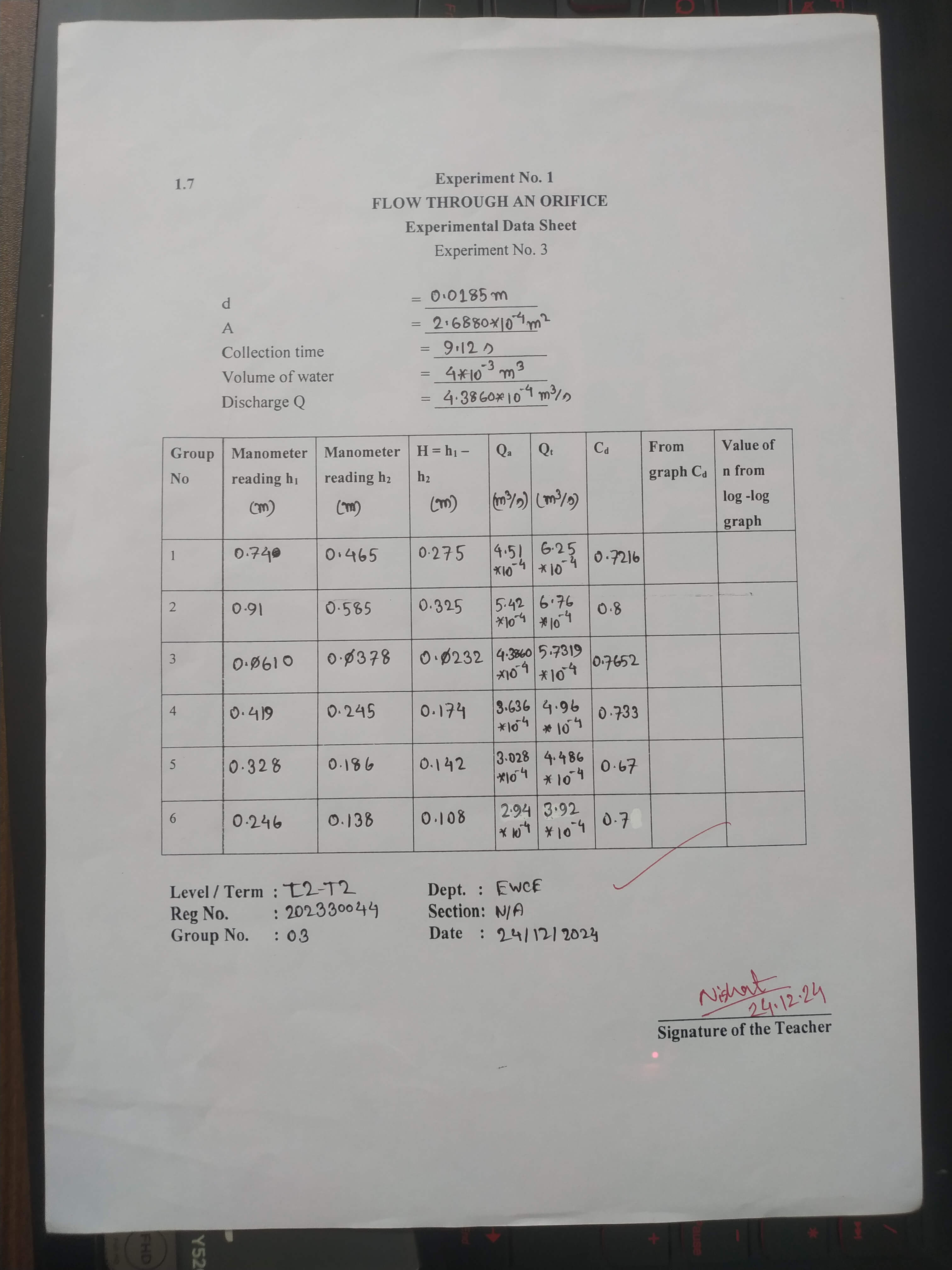
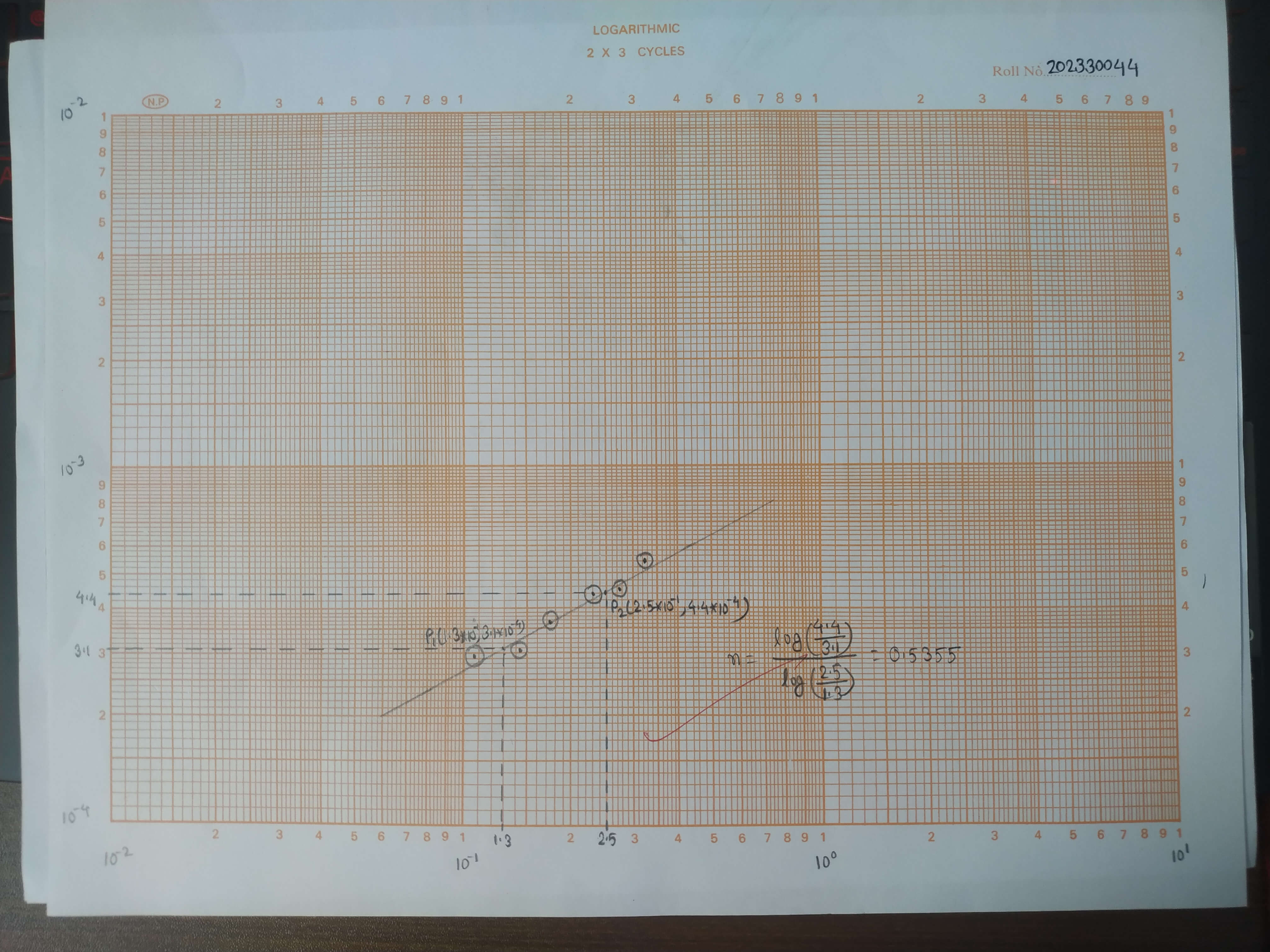
# Datasheet and graph
# Calculation
For the two points ($P_1$ and $P_2$) on log-log graph, we get:
1. $H_1 = 1.3\times 10^{-1}$, $Q_1 = 3.1\times 10^{-4}$
2. $H_2 = 2.5\times 10^{-1}$, $Q_2 = 4.4\times 10^{-4}$
The exponent of $H$ can be calculated using the formula,
$$
n = \dfrac{\log{\dfrac{Q_2}{Q_1}}}{\log{\dfrac{H_2}{H_1}}}
$$
Applying the value of $Q_1$, $Q_2$, $H_1$, and $H_2$, we can get,
$$
n = \dfrac{log{\dfrac{4.4\times 10^{-4}}{3.1\times 10^{-4}}}}{\log{\dfrac{2.5\times 10^{-1}}{1.3\times 10^{-1}}}} = 0.536
$$
The calibration parameter $C$ can be calculated using the formula,
$$
C = 10^{\log{Q} - n\log{H}}
$$
Applying the value of $n$, $Q = Q_2$ and $H = H_2$, we can get,
$$
C = 10^{\log{4.4\times 10^{-4}} - 0.536\log{2.5\times 10^{-1}}} = 9.250\times 10^{-4}
$$
Comparing with the calibration equation $Q_a = CH^n$ and $Q_a = C_dKH^n = C_dA\sqrt{2gH}$, the average coefficient of discharge can be calculated using,
$$
C_d = \frac{C}{A\sqrt{2g}}
$$
Applying the value of $C$, $A$, and $g$, we can get,
$$
C_d = \dfrac{9.250\times 10^{-4}}{2.688\times 10^{-4}\sqrt{2\times 9.8}} = 0.777
$$
# Discussion
In this experiment, the orifice meter was calibrated by determining the average coefficient of discharge $C_d$ and the exponent $n$. The values of average $C_d$ and $n$ were determined to be $0.777$ and $0.536$, respectively. For consecutive use of this meter, the following formula can be used to calculate actual discharge:
$$
Q_a = C_dQ_{th} = C_dA\sqrt{2g}H^n = C_dKH^n = CH^n = 9.250\times 10^{-4}H^{0.536}
$$
It is to be noted that, these constants are valid for the orifice meter used only.
## Possible errors
There are several possible sources of errors when performing this experiment:
1. Poor calibration or damaged apparatus can lead to inaccuracies.
2. Pressure head readings from manometer has direct impact by parallax errors.
3. Measurements of actual discharge require both timing and volume, both of which are error prone due to the nature of human.
## Comment on result
The experiment yielded values of $C_d$ ranging from $0.67$ to $0.80$, with average $C_d$ from graph being $0.777$. The theoretical expectation for this orifice meter is that, $C_d$ should be within $0.59$ to $0.65$ due to high frictional losses:
$$
H = H_{actual} + H_L
$$
Here, $H_L$ is the head loss due to frictions. Since $H$ is considered during the calculation of $Q_{th}$, this higher value of $H$ produces a higher value for $Q_{th}$, causing it to be significantly higher than $Q_a$ which leads to $C_d$ being low.
Given both experimental $C_d$ and consequently the value from graph exceeds the expected value of $C_d$, it is possible that:
1. The orifice meter was well-designed with minimal head loss (therefore, energy loss) than expected.
2. On the contrary, it could be due to misreading of pressure heads.
3. Errors in measurements of $Q_a$, such as timing error.
4. The apparatuses were damaged.
# Practice problems
## $C_v$, $C_c$, and $C_d$
| Coefficient | Description | Formula | Average value |
| -------------------------- | ------------------------------------------------------------------------------------ | --------------------------------- | -------------------------- |
| Coefficient of velocity | The ratio between actual velocity ($V_{act}$) and theoretical velocity ($V_{th}$). | $$C_v = \dfrac{V_{act}}{V_{th}}$$ | 0.95 to 0.99 |
| Coefficient of contraction | The ratio between area of vera contractor ($A_c$) and area at orifice ($A$). | $$C_c = \dfrac{A_c}{A}$$ | 0.61 to 0.69; average 0.64 |
| Coefficient of discharge | The ratio between actual discharge ($Q_{act}$) and theoretical discharge ($Q_{th}$). | $$C_d = \dfrac{Q_{act}}{Q_{th}}$$ | 0.59 to 0.65; average 0.62 |
These coefficients depends on:
1. Shape of the orifice — circular, rectangular, triangular or square.
2. Size of the orifice — small or large orifice.
3. Shape of edge — sharp edged, bell mouthed or rounded edge.
4. Fluid properties like viscosity and compressibility.
5. Flow conditions — turbulent (higher $Re$) or laminar (lower $Re$).
## Submerged orifice
A submerged orifice is an orifice where both the upstream and downstream openings are submerged under liquid, leading to flow due to the difference in pressure or head between the two sides.
The average values of coefficient of velocity, coefficient of contraction, and coefficient of discharge for submerged orifice is 0.95 to 0.99, 0.62 to 0.67 and 0.58 to 0.62 respectively.
## Actual discharge less than theoretical discharge
The actual discharge through an orifice is significantly lower than theoretical discharge due to high frictional loss, $H_L$.
$$
H = H_{act} + H_L
$$
The orifice meters creates an abrupt restrict in fluid flow at the edge of orifice, causing severe turbulence and high energy loss (thus head loss).
Since, discharge is proportional to pressure head ($H$), this head loss reduces discharge.
$$
Q_{th} = A\sqrt{2gH}
$$
## Vena contraction and its formation
Vena contractor is the point in a fluid jet where cross sectional area is the smallest. At this point, velocity is the highest and pressure head is the lowest. Streamline is parallel to the axis of flow channel. Vena contractor forms as the fluid stream converges at the edge resulting in a narrower stream jet.